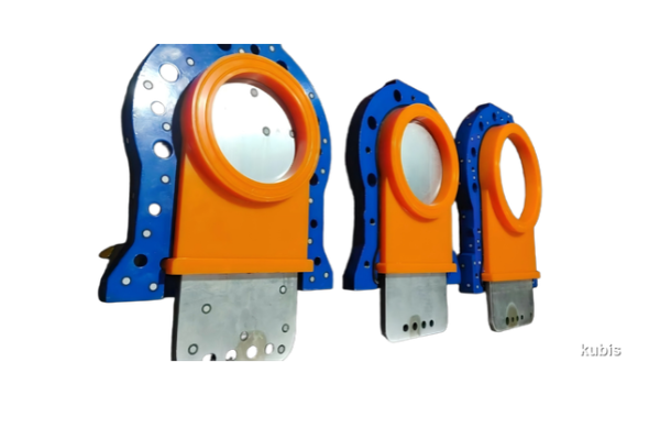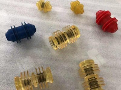
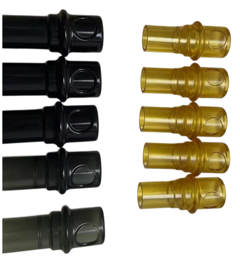
An industrial air blow gun nozzle sleeve adds a replaceable contact surface around a metal nozzle to help reduce marks on finished parts and fixtures. It must stay in position, leave the main outlet and any side or relief ports clear, and still fit after repeated use and exposure to shop fluids. Cast polyurethane is one candidate when the sleeve needs a custom bore or a wear-resistant contact face.
This guide is for equipment designers, maintenance teams and buyers. It covers what to measure, how to compare materials and what to verify on the complete tool before releasing a sleeve.
What an Air Blow Gun Nozzle Sleeve Does
Operators often work close to machined faces, painted panels, plastic housings or fixtures when clearing chips or liquid. If a bare metal nozzle touches the workpiece, its edge can leave a mark. An external sleeve puts a replaceable contact surface at that interface. Confirm the benefit with a representative finished part: even a soft sleeve can scratch a surface if a sharp chip embeds in it.
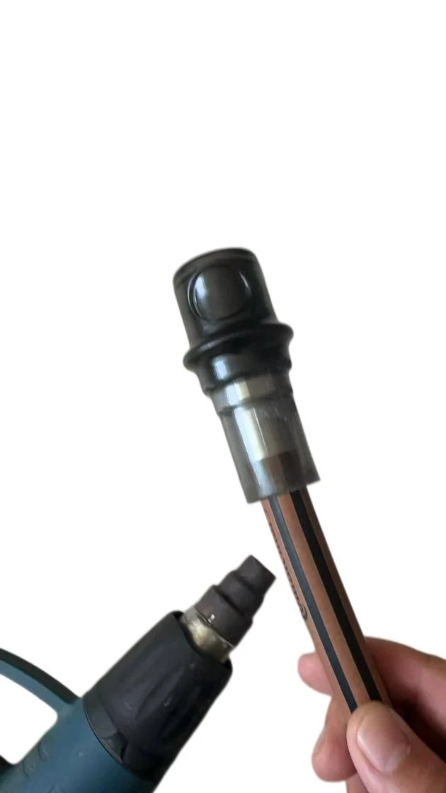
Preserve the original safety features. The sleeve is a contact accessory. Keep the nozzle’s outlets, vents, guards and markings functional, and review the tool manufacturer’s instructions before adding it. If the manufacturer prohibits the change, do not use the sleeve on that tool.
For U.S. general-industry cleaning, OSHA 29 CFR 1910.242(b) requires compressed air to be reduced to less than 30 psi and used with effective chip guarding and personal protective equipment. OSHA’s interpretation explains how the nozzle pressure requirement applies under static or dead-ended conditions. A sleeve does not establish compliance. The employer must evaluate the complete tool and how it is used; follow the applicable local requirements for other markets.
Design the Fit and Keep Air Openings Clear
Define the installed position on the drawing
Measure the approved nozzle’s outside diameter and tolerance, end profile, available engagement length and the location of every functional opening. Identify a reference face and define how far the sleeve can move forward or backward. For a friction fit, check both the tightest combination for installation force and the loosest for retention. If a compatible assembly lubricant is used, include it in the retention test. Use the custom part specification checklist to record dimensions, tolerances and acceptance criteria.
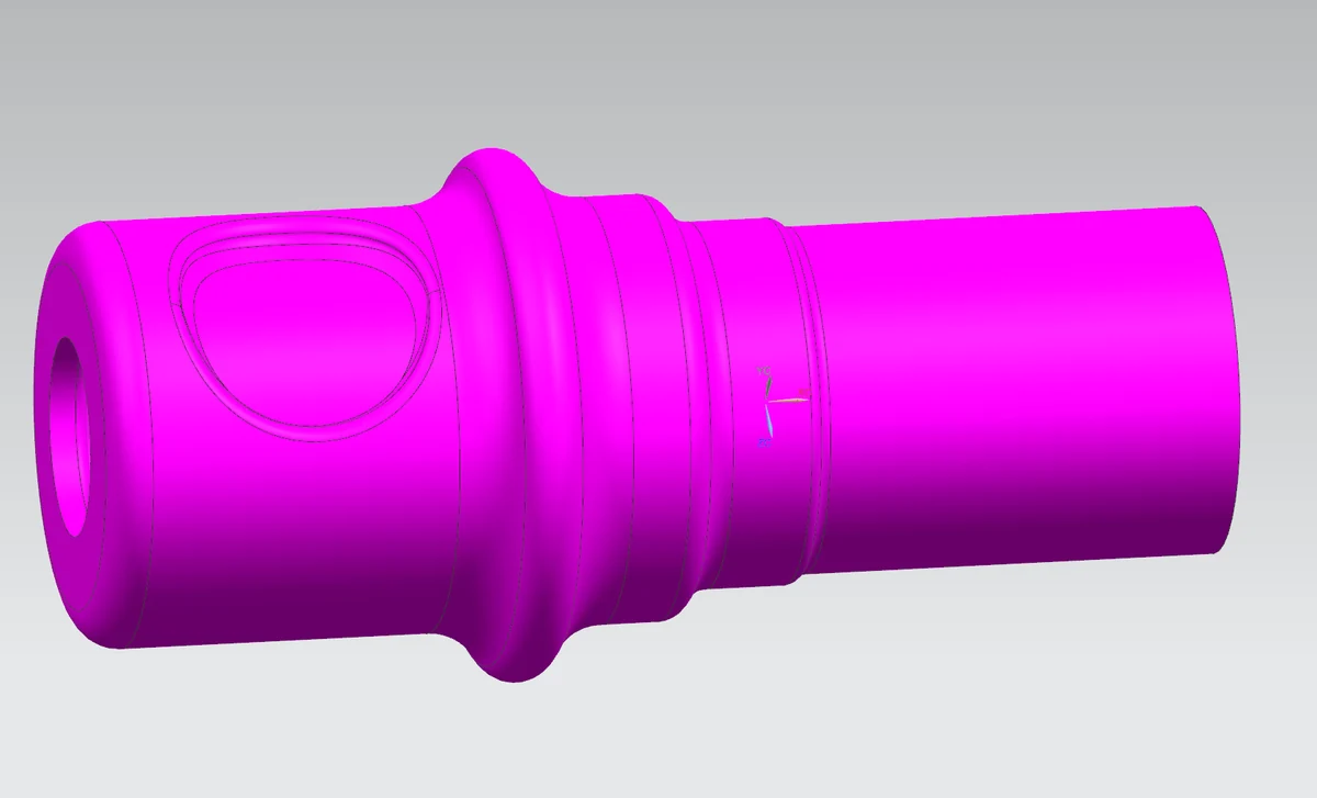
Where the approved nozzle geometry allows it, an existing shoulder can locate the sleeve, and a witness mark can make position easier to inspect. A witness mark does not retain the sleeve. Do not drill, groove or otherwise change the metal nozzle without the manufacturer’s approval.
Set clearances at the outlet and side ports
Specify the minimum installed front opening, maximum sleeve coverage and the clear zone around any side ports or relief features. Where a window is needed, review its corner radii and remaining wall so repeated installation does not create a tear path. Check clearance at both extremes of permitted rotation or movement and after conditioning, wear and representative contact. A sleeve that looks clear on the bench can roll, shift or deform when fitted.
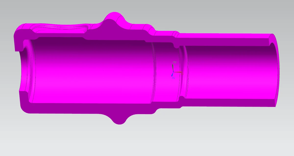
Design example: On a nozzle with radial vents, a longer sleeve may offer more engagement but also reach the vent zone at its forward tolerance limit. Shorten or positively locate the sleeve on approved geometry, then recheck both retention and complete-tool function. Do not accept the change solely because the vents are visible on one sample.
Compare Cast Polyurethane, TPU, Rubber and Plastics
Compare actual grades in the same nozzle and workpiece setup. A sleeve needs enough compliance to avoid marking the part and enough dimensional stability to stay out of the air path. Hardness, wall thickness, bore fit and surface finish work together. Our polyurethane processing comparison explains how cast and thermoplastic routes differ.
| Candidate | When to evaluate it | What to verify |
|---|---|---|
| Cast polyurethane (CPU) | A custom bore, wall profile or wear surface is needed. | Installation force, recovery, wear at the contact face and tear resistance around thin sections. |
| Thermoplastic polyurethane (TPU) | A thermoplastic molding route suits the geometry and planned quantity. | Molded bore variation, deformation, retention and performance after conditioning. |
| Rubber | A specific elastomer compound is being considered for a compliant contact surface. | Fit after exposure, aging, marking or transfer, and stability around openings. |
| Engineering plastic | A firmer machined or molded sleeve is being considered for a surface that tolerates it. | Contact marks, edge damage and retention after wear or repeated removal. |
Specify the actual coolant, oil, wash fluid or cleaner, its concentration, temperature and exposure time. Do not assume compatibility from a material family name. For shortlisted cast grades, see the cast polyurethane material selection guide and the polyurethane temperature guide.
Diagnose Sleeve Failures by Where They Start
| Observed problem | Likely checks | Design or maintenance response |
|---|---|---|
| Sleeve moves forward | Engagement length, bore fit, oil exposure and direction of contact. | Recheck retention at the loose tolerance limit and after exposure; review a permitted locating feature. |
| Rear edge splits during fitting | Lead-in shape, burrs, tight-end interference and wall thickness. | Correct the sleeve lead-in or fit and review the assembly method. |
| Opening rolls or deforms | Installed position, local wall thickness, swelling and contact load. | Remove the affected tool from service for review. Verify clearances and function before release. |
| Workpiece still shows marks | Embedded chips, material transfer, exposed metal or excessive contact force. | Inspect a representative surface under the same handling and cleaning conditions. |
Validate the First Article on the Complete Blow Gun
Agree on acceptance limits with the equipment owner before testing. Use nozzles representing the relevant dimensional limits and keep a record of the nozzle and sleeve revisions.
- Check fit: record critical dimensions, installation and removal force as applicable, installed position and retention after repeated fitting.
- Check the air path: have the responsible equipment or safety team verify the assembled tool under the manufacturer’s instructions and an approved test procedure, including any required obstructed-nozzle checks. Inspect foreseeable displacement or deformation.
- Check the workpiece: use a representative finished surface or witness panel to assess scratches, dents, material transfer and debris.
- Check conditioned parts: expose the sleeve to the relevant fluid and temperature, then repeat fit, retention and clearance checks. ISO 1817:2026 provides liquid exposure methods for suitable vulcanized or thermoplastic rubber specimens within its scope. Agree on an appropriate method for the chosen material and separately verify the finished part. The material and component testing guide describes how to separate these two checks.
- Set maintenance limits: after representative wear and removal cycles, agree when to replace a sleeve for movement, tears, contamination or opening distortion. Record how the operator checks position.
Air Blow Gun Nozzle Sleeve FAQ
1. Is the softest sleeve best for a finished surface?
No. It also needs to stay in position and retain its opening. Test for contact marks and embedded particles as well as fit.
2. Can a protective sleeve fit a safety nozzle?
Only if the tool manufacturer permits it and complete-tool verification shows the relevant safety functions still work.
3. Can cast polyurethane replace a TPU or rubber sleeve directly?
Do not assume interchangeability. Check the bore fit, retention, air clearances and exposure response of the proposed grade and part.
4. What should be measured on the nozzle?
Record the outside diameter and tolerance, end shape, engagement length and the position of the main outlet and any side or relief ports.
5. When should a sleeve be replaced?
Follow the approved inspection and replacement criteria. Movement, cracks, embedded debris or distortion near the openings require attention.
6. Does a sleeve make a blow gun OSHA compliant?
No. The employer must evaluate the assembled tool and its use, including nozzle pressure, effective chip guarding and personal protective equipment where applicable.
Request a Custom Nozzle Sleeve Review
Send Kubis Tech the nozzle model and drawing or clear photos, with each outlet and relief port marked. Include the workpiece finish, pressure and duty, temperatures and fluids, photos of the current problem, and sample and production quantities. We can review the custom cast polyurethane part, propose what to check on the prototype, and identify the dimensions to confirm before quoting. Complete-tool approval remains with the responsible equipment owner.
Send your nozzle drawing for a sleeve review
Further Reading on LinkedIn
For additional engineering perspectives on air blow gun nozzle protection, polyurethane material selection, and custom sleeve design, read our related article on LinkedIn: Air Blow Gun Nozzle Sleeves: Why a Small Protective Component Deserves More Engineering Attention.